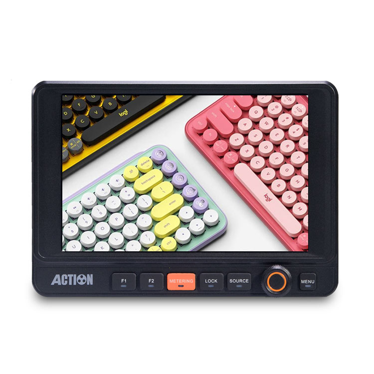
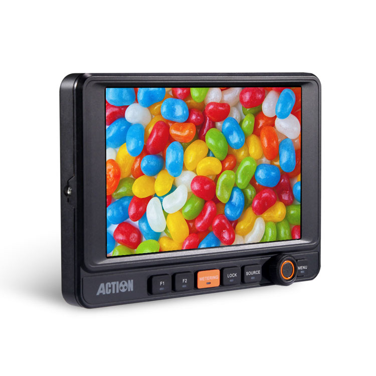
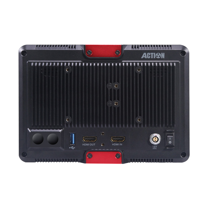
HL-701HM
Category:Monitor
Screen Size:7 inch
Features
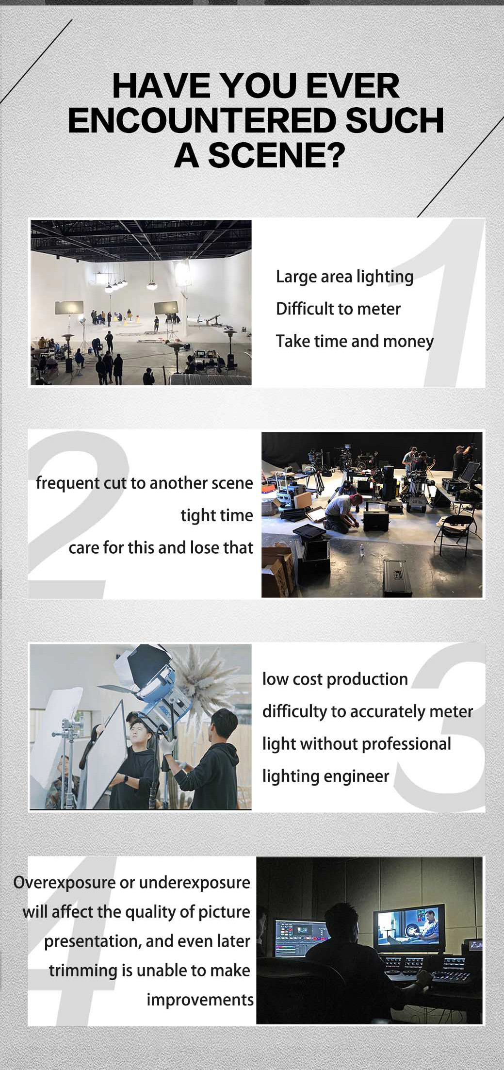
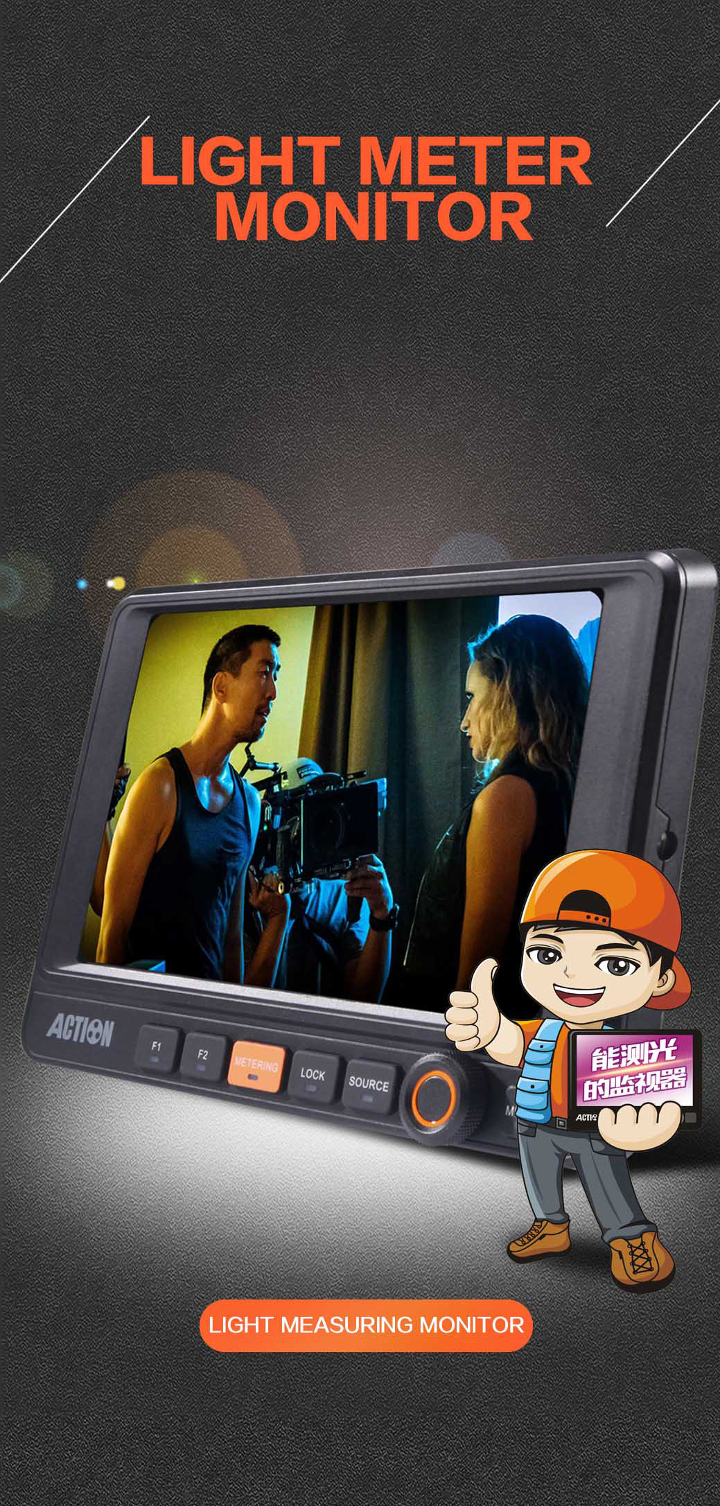
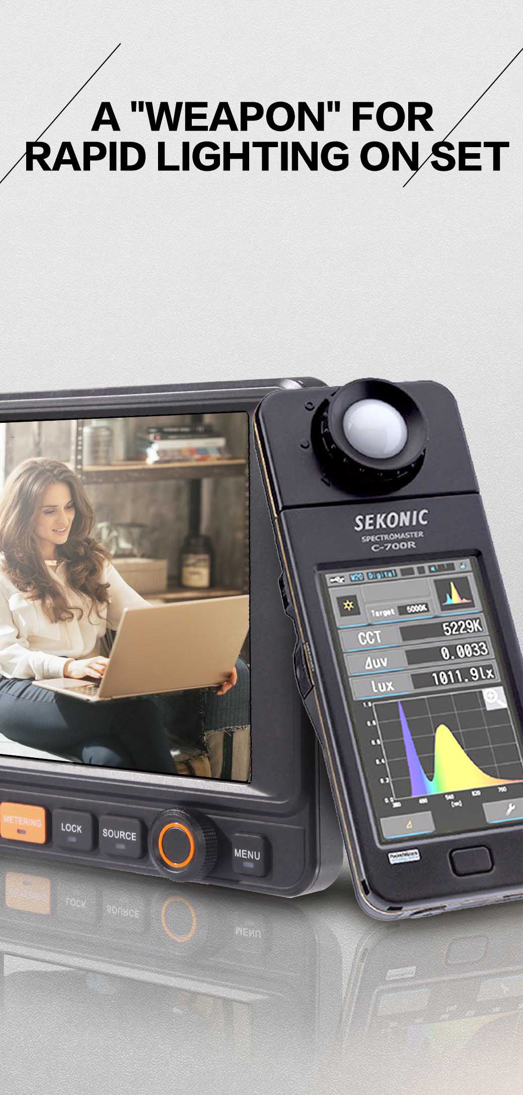
- Monitor that can measure light, only one second, real-time reproduction signal.
- Original closed detection technology, expands the professional use of the monitor, assisting lighting sects to reduce cloth error rate.
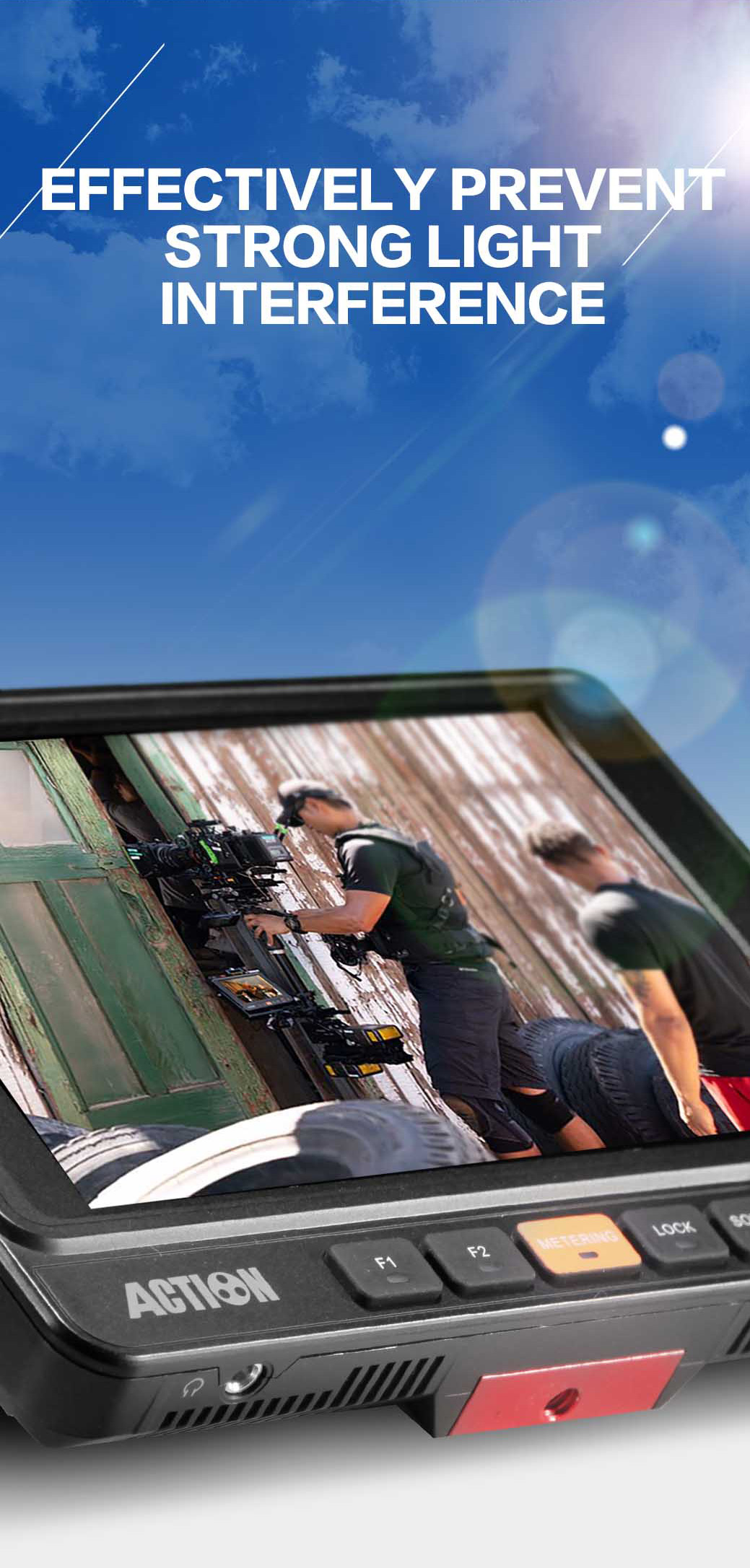
- A new generation of light refractive gathering technology is used. The light intensity is under 100000lux, and it is still necessary to display a clear picture without the need to make the cover.




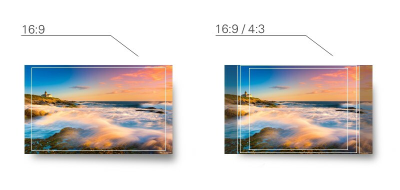
Safe & Area Marker
Usage:
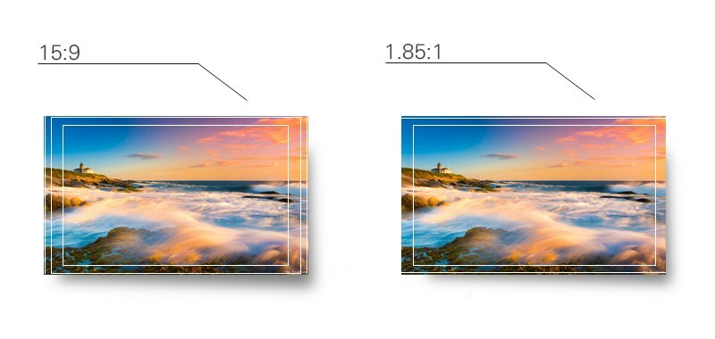
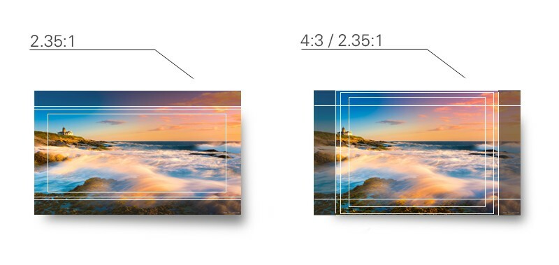
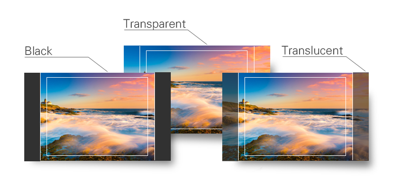
Image overflow or cutoffs can be checked using this feature. This is helpful during “Pan and Scan” as image is prepped for various broadcast markets. Ruige monitors have selections for Safety Marker Scales, Title Scales, Transform Scales and Center Cross. This is helpful for composition during shooting or title placement.
Over scan
Usage:
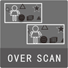
Overscan is often used to programing for TV broadcast.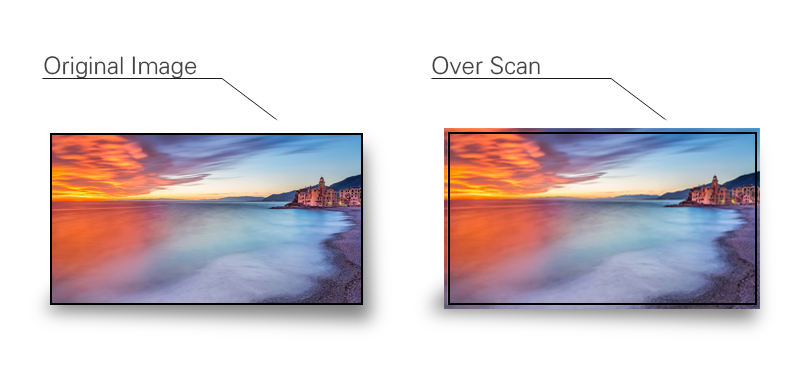
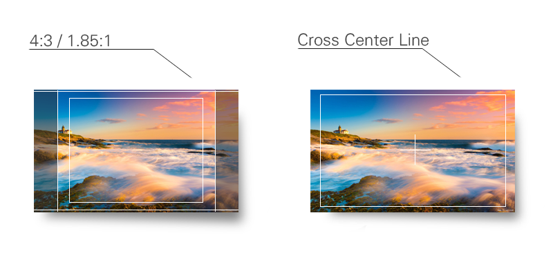
Marker Scale
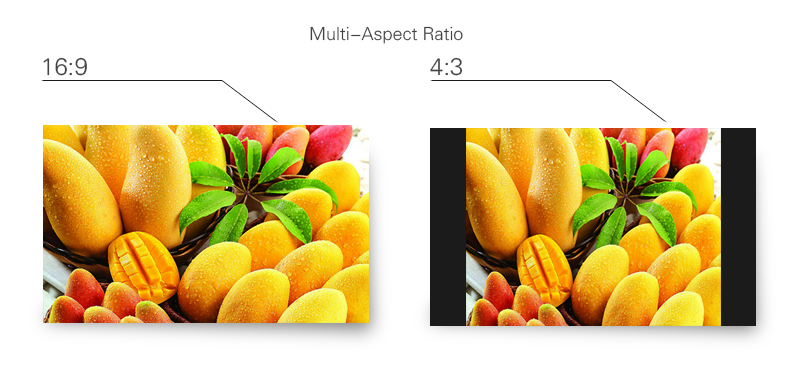
Usage:
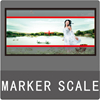
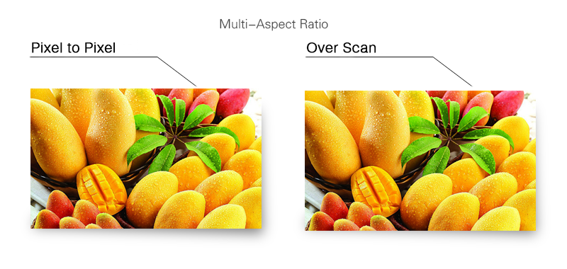
In order to adjust for correct scanning users can choose different Aspect ratios. Selections are: 16:9, 4:3, Letterbox, Pixel-to-Pixel, Over Scan and Built-in Scan.
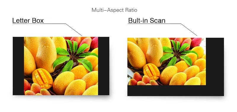
Beyond the normal image,the blanking area of field/horizontal signal is shown in screen.
In SDI signal, there are many useful information embedded in the blanking area of field/horizontal signal. For example, SDI Audio, CC (Closed Caption),etc.. It is necessary to check the information in the blanking area to make sure if these information has been embedded successfully.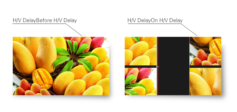
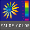
Luminance levels can be represented using False Color on the screen. It represents the amount of exposure explained as color values ranging from Blue to Green to Yellow to Red.
Usage:
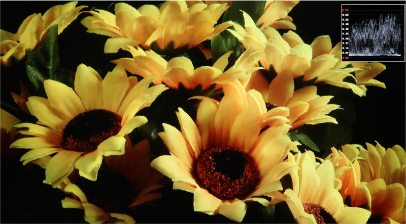
False Color is used to assist in setting the camera exposure. Blue (cool color) indicates a low exposure, a darker blue indicates an even lower exposure. Red (warm color) indicates a high exposure and a deeper red indicates an even higher exposure. Green and Yellow are in between. A scan feature allowing the image to be offset to the upper left revealing the Luminance Waveform on the upper right makes it easy to identify parts of the picture which may exceed standards.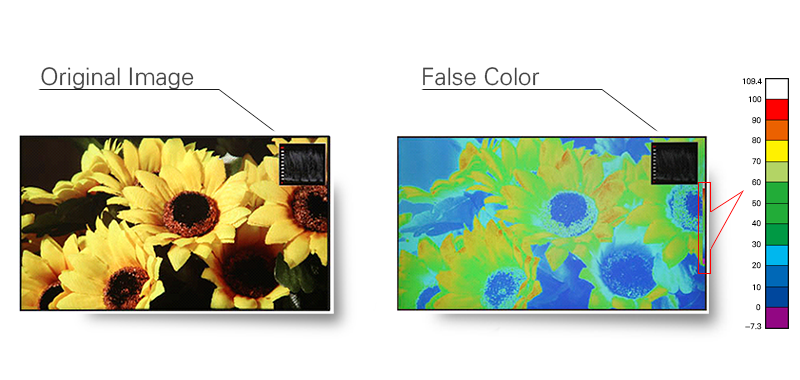
Luminance Waveform
The luminance waveform can be superimposed over picture (see below). The Y-axis represents the luminance level. There are two indicators; one at 100% and one at 700mv.
Usage:
The Luminance waveform is mainly used to read the value of the Y signal. This is helpful for setting Camera Iris levels.

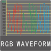
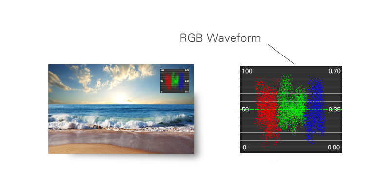
RGB waveform can accurately reflect the overflow of the two ends. the RGB parade waveform shows how strong each color signal is in its own channel.
Usage:
Any of the three channel overflow on the left or right of the parade, it results in the mixed RGB overflow. Then the details of light or dark part will lost. each one is pegged at 100% where it appears in its channel. The channel shows red at 100% where the red patch appears, but zero where the green and blue patches appear, etc.
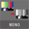
Mono(chrome) displays only the Y portion of the video signal
Usage:
Human Eyes are more sensitive to the luminance signal therefore many viewfinders and small monitors have this function.
16 channels of embedded audio in the SDI video signal can be decoded and 8 selective channels can be shown on the screen at the same time. The Volume unit shows both VU and PPM.
Usage:
The Volume unit is used for measuring audio levels and calibration. This is helpful for making sure that audio levels are within technical requirements and specifications.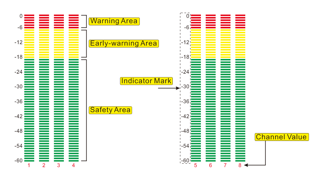
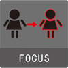
A red peaking filter is used for Focus Assistance. It is represented as a red line around sharp edges. The edge color can be changed if desired; available colors are red, blue, green, yellow and white.
Usage:
Using a red peaking filter aids in the ability to quickly focus or refocus a shot. As the photographer zooms into focus his shot sharp edges will be represented as red lines.
The zebra is suggested that the photographic exposure is a highlight indicator, and the aperture can be controlled according to the zebra tips when shooting with a manual aperture.
Usually when the brightness of the subject exceeds the maximum brightness (different types of models) that the camera can accommodate (different, this value is different), the zebra is started, so, when the aperture is adjusted, the subject should be the brighteree Slightly with zebras, while other parts have no zebra, which can be accurately exposed. If the spot is too much, the exposure is excessive; if there is no zebra pattern any part of the image, the image will be insufficient. Now some cameras are adjustable, usually adjusted between 60% and 100% of the highest brightness, and can be selected according to their own habits.
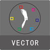
There are 6 fixed vector measurement points; R, Mg, B, Cy, G and Ye. Neutral Colors (Black, White and Grey) are represented in the center of the vector scope. The direction is outward from the center and reflects the degree and amount of saturation; the further away from the center the higher the amount of color.
Usage:
The vector scope shows the distribution of color within the video signal and can be used to determine the amount of color, correct color phase alignment and color analysis of objects within the picture.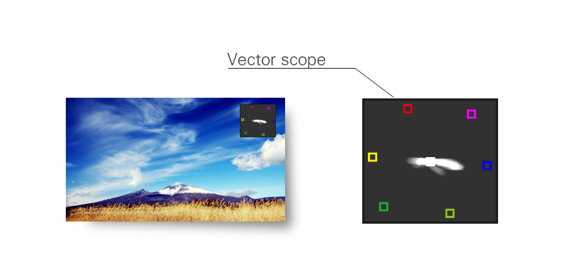
GPS in Video
Rapid positioning for out of range indicator
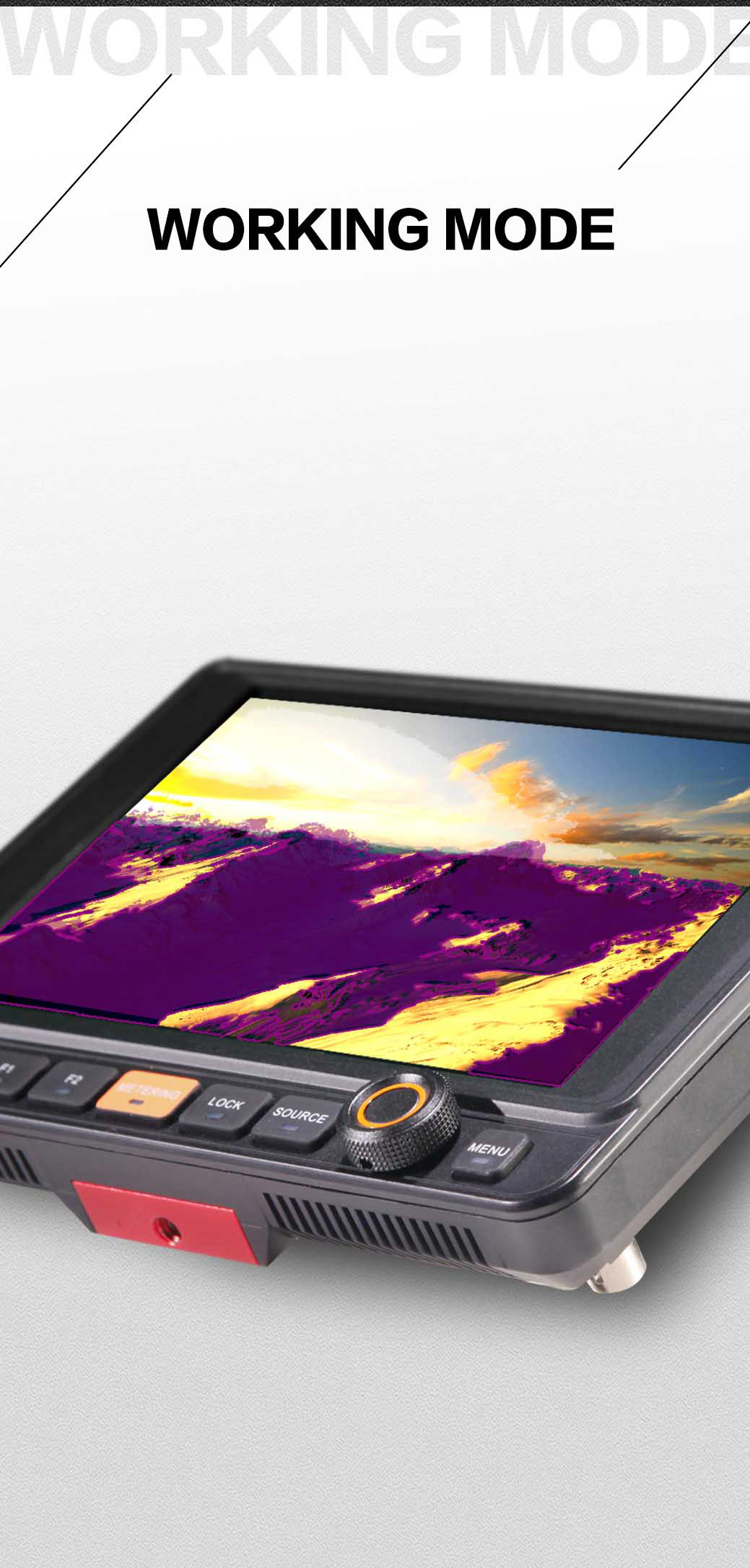
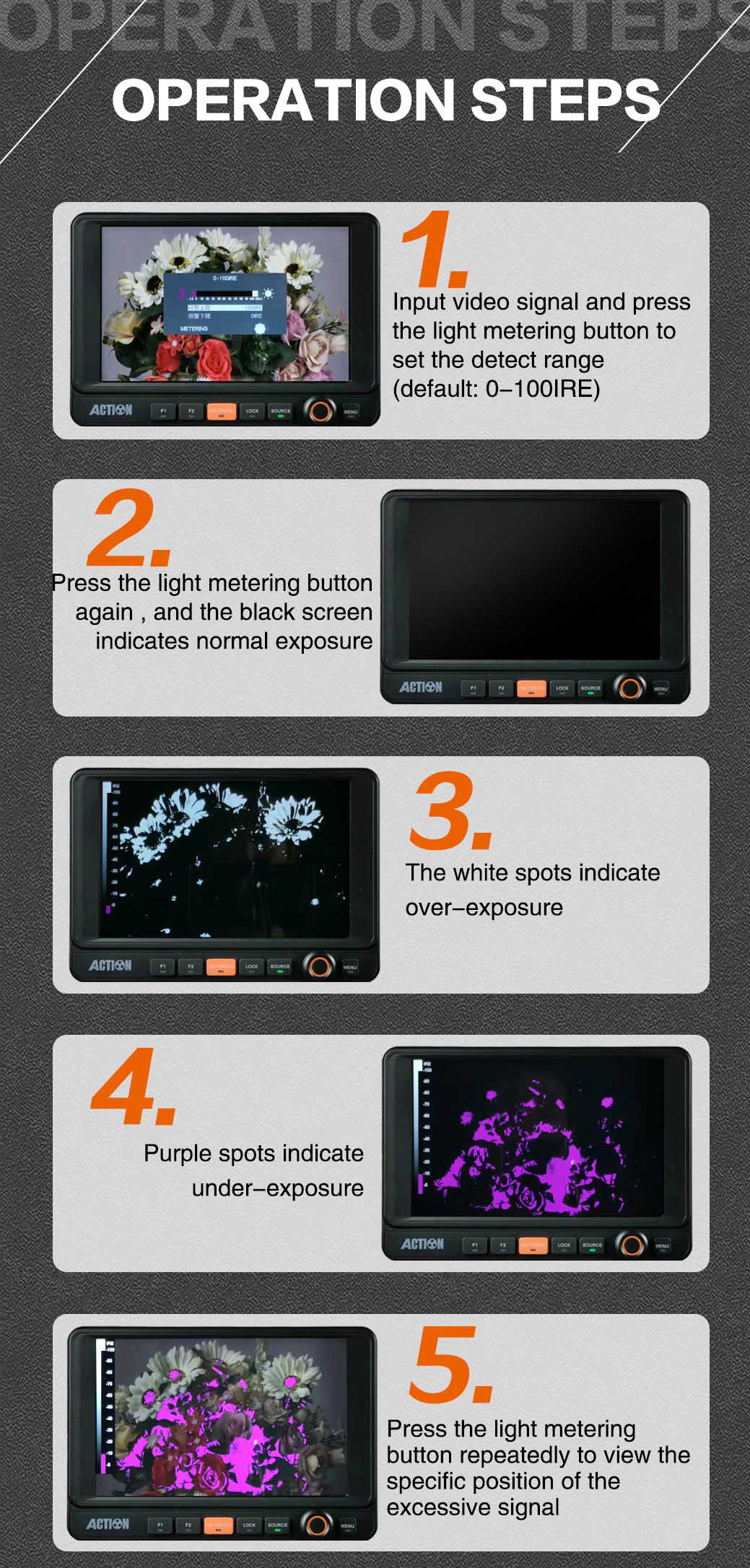
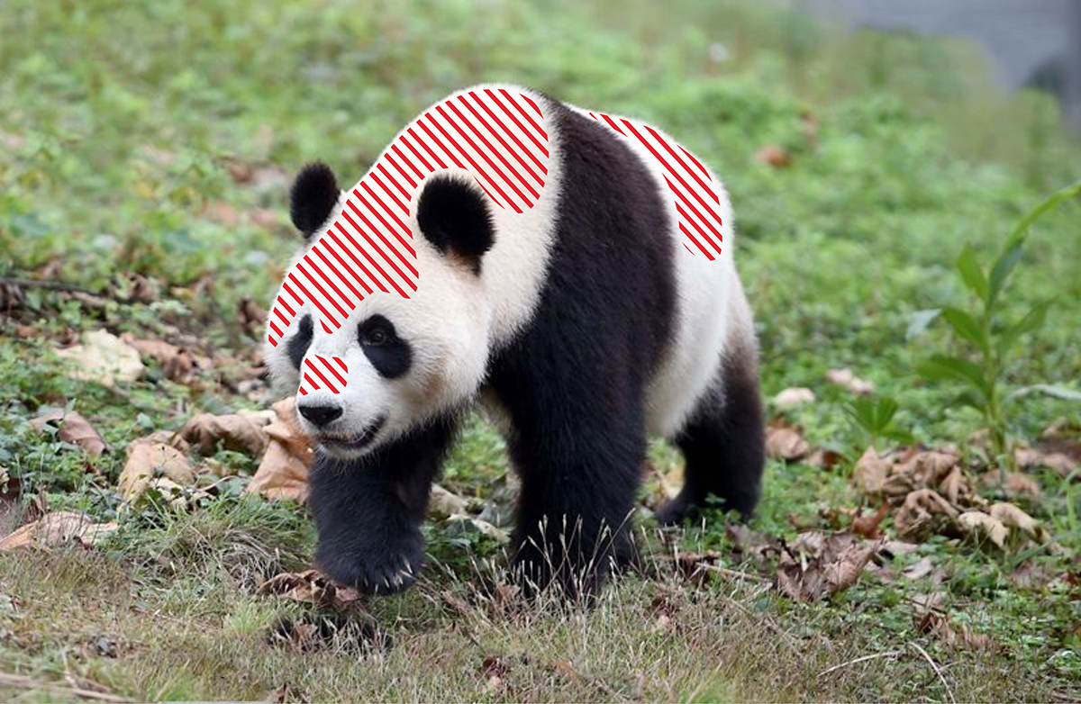
“Exposure analysis” function gives the user the ability to do fast out of range checks. When the image becomes more complex with out of range colors, it becomes too inconvenient to see.
The design inspiration of this function is based on x-ray machines and body scanners at airports. The black color indicates hard items and the softer items are represented with White and purple. These colors can be isolated in one second by contrasting with “Exposure Analysis” when switched on.
Case in point, security checks at airport are lacking due to subjective human factors. With Rapid positioning for out of range indicator allows for 100% accuracy. However, the end user has the freedom to not use this function for that artistic professional look.
